The FKM guideline is now an indispensable tool for many engineers and designers for the computational strength assessment of machine components. Chapters 3 and 4 in particular provide a structured methodology for performing static strength verification as well as fatigue strength verification – two critical assessments for component safety. In this article, we examine the key steps of application, specific advantages over other standards, and relevant practical aspects for FEA-based simulations. A wide range of materials can be used with the FKM guideline for verification, including typical steels, aluminum alloys, and various cast materials. A fundamental distinction is made between welded and non-welded areas.
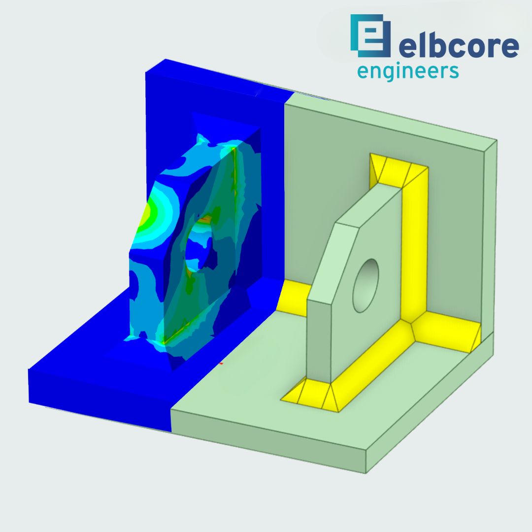
Static Strength Verification and the Plastic Support Factor
Chapter 3 of the FKM guideline focuses on assessing component safety under static loading. The central concept here is the evaluation of allowable stress while considering possible plastic reserves. The plastic support factor npl plays a key role in this context. It describes the ability of a structure to carry additional loads beyond the elastic limit by utilizing plastic deformations. Additional influences such as elevated temperature are accounted for within the guideline by increasing the overall safety factor.
Practical application in FEA simulations requires careful modeling: The selection of appropriate material laws, particularly elastic-plastic models, is critical. The allowable stresses for verification, as defined in Table 3.6 of the guideline, must be adjusted taking npl into account. This differentiated approach enables more economical component design without compromising safety – a significant advantage over standards that use purely elastic verification concepts.
Fatigue Strength Verification and Allowable Cycle Numbers
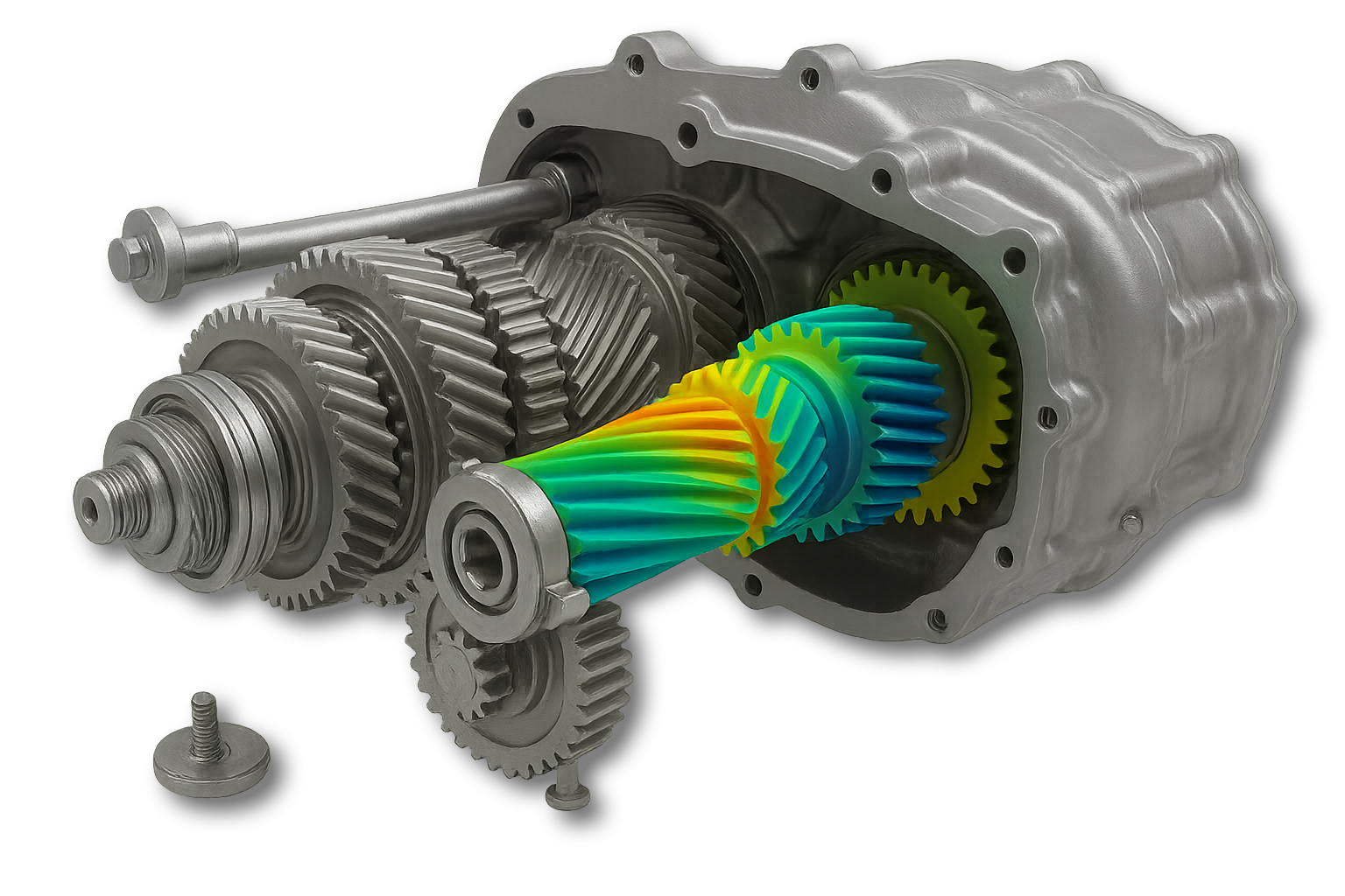
Chapter 4 of the guideline is dedicated to the assessment of fatigue or endurance strength under oscillating or alternating loading. Compared to static strength verification, the determination of allowable stress amplitude is considerably more comprehensive and takes into account significantly more parameters, such as surface roughness or a thickness factor for welded sheets. Depending on the required number of cycles demanded of the component, verification is performed either for fatigue or endurance strength.
In practical application, careful modeling of notches and geometric transitions in FEA models is particularly critical. Excessively coarse mesh resolution or neglecting local stress concentrations can lead to significant deviations. Our experience shows that local mesh refinement and targeted use of submodeling techniques help to accurately capture these effects in simulation.
Distinction from Other Standards and Validation Status
Unlike more general standards such as Eurocode 3 or specific DIN standards, the FKM guideline provides a material- and load-specific methodology that delivers consistent assessment approaches for both static and dynamic loading. Particularly in the transition from elastic to plastic behavior and under multiaxial loading, the FKM guideline enables a more detailed and practical assessment. As Wagner et al. emphasize: “The FKM guideline has proven to be a practical tool for industry, but requires careful application, especially in the transition from elastic to plastic behavior and under multiaxial loading.” (Wagner et al., 2015).
Our experience in simulating complex components – for example, machine components under cyclic loading or flow components with temperature effects – demonstrates that the FKM methodology offers clear advantages over overly conservative or too generic assessment procedures due to its flexibility and validation basis.
Application Practice: Specific FEA Guidelines
In the practical calculation process, we begin with an elastic linear FEA analysis to identify the relevant stress states. Subsequently, if necessary, the support factors are determined and verification is performed according to FKM specifications. Especially for dynamic and cyclic loads, we place particular emphasis on the precise modeling of component edges, notches, and welds to correctly represent the influences on fatigue strength.
An example from our practice: For a company in the fan industry, we performed a fatigue strength verification for the rotor blade mount. Through targeted FEA modeling and the implementation of various optimization measures, we were able not only to successfully verify fatigue strength but also to significantly streamline the structural design – a clear advantage in terms of material costs and service life prediction.
Conclusion: FKM-Compliant Simulation as a Competitive Advantage
The FKM guideline provides a practical framework with its clearly defined methods for static and dynamic strength verification, which demonstrates its strengths particularly in virtual product development. The targeted application of this methodology in combination with high-precision FEA simulations enables safe, optimized, and simultaneously economical designs.
If you want to develop your products at the highest technical level or optimize your existing components for load-appropriate performance, we are happy to support you with our expertise in computational strength assessment according to FKM and state-of-the-art FEA simulation. Contact us – together we will find the optimal solution for your requirements.
References
- Wagner, L., et al. (2015). FKM Guideline: Strengths, Limitations and Experimental Validation. Procedia Engineering, Volume 133, 418–425.